
|
Software to facilitate your work |
| Home |
| Software |
| Shareware |
| Download |
| Purchase of the software |
| Community |
| Contact |
| Partners |
| Site map |


|
SOFTWARE |


|
OPCutting - Tutorial of creation of a complex cutting plan |
|
This page describes, step by step, the creation of a complex cutting plan. You can print the page and in order to have assistance when making your first complex cutting plan with the panel cutting software. You can watch here a video made with the French version of OPCutting that shows the creation of a complex cutting plan. |
Download and try OPCutting for free for 30 days!
|
Reminder to users who have arrived on this page from a search engine. OPCutting is a panel cutting software for determining the layout of parts on the wood panels or sheets of other materials, so as to reduce the number of panels used and to limit the number of unusable offcuts. |
|||||||||||||||||||||||||||||||||||||||||||||||||||||||||||||||||||||||||||||||||
About this tutorial |
|||||||||||||||||||||||||||||||||||||||||||||||||||||||||||||||||||||||||||||||||
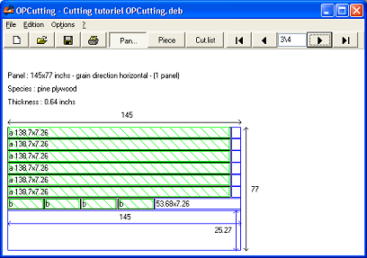 |
The tutorial explains the use of OPCutting with an example comprising several panels with different materials and different formats in which we must cut several parts. |
||||||||||||||||||||||||||||||||||||||||||||||||||||||||||||||||||||||||||||||||
| < Previous | |||||||||||||||||||||||||||||||||||||||||||||||||||||||||||||||||||||||||||||||||
The cutting list chosen for example |
|||||||||||||||||||||||||||||||||||||||||||||||||||||||||||||||||||||||||||||||||
| The list below gives the dimensions and characteristics of the parts we want to cut: | |||||||||||||||||||||||||||||||||||||||||||||||||||||||||||||||||||||||||||||||||
We cut these parts into panels having the following formats:
|
|||||||||||||||||||||||||||||||||||||||||||||||||||||||||||||||||||||||||||||||||
| < Previous | |||||||||||||||||||||||||||||||||||||||||||||||||||||||||||||||||||||||||||||||||
Begin the creation of the cutting plan |
|||||||||||||||||||||||||||||||||||||||||||||||||||||||||||||||||||||||||||||||||
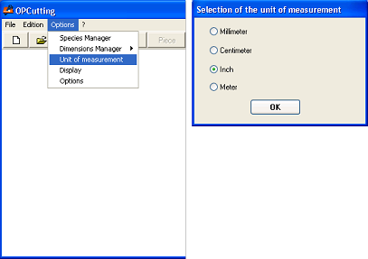 |
To create your complex cutting plan with the panel cutting software, you must first verify that the unit of measurement used by OPCutting is the "Inch" (see software user guide). |
||||||||||||||||||||||||||||||||||||||||||||||||||||||||||||||||||||||||||||||||
| < Previous | |||||||||||||||||||||||||||||||||||||||||||||||||||||||||||||||||||||||||||||||||
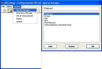 |
You must create three species of wood used in the cutting plan given in the second table in the section "The cutting list chosen for example", if these types of wood are not already set in the software. |
||||||||||||||||||||||||||||||||||||||||||||||||||||||||||||||||||||||||||||||||
| < Previous | |||||||||||||||||||||||||||||||||||||||||||||||||||||||||||||||||||||||||||||||||
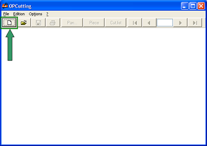 |
To start creating your cutting plan, just click on the button showing a blank page. |
||||||||||||||||||||||||||||||||||||||||||||||||||||||||||||||||||||||||||||||||
| < Previous | |||||||||||||||||||||||||||||||||||||||||||||||||||||||||||||||||||||||||||||||||
Data entry of the cutting plan |
|||||||||||||||||||||||||||||||||||||||||||||||||||||||||||||||||||||||||||||||||
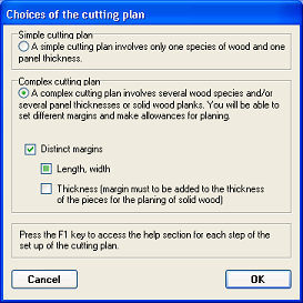 |
Select the type of cutting plan. |
||||||||||||||||||||||||||||||||||||||||||||||||||||||||||||||||||||||||||||||||
| < Previous | |||||||||||||||||||||||||||||||||||||||||||||||||||||||||||||||||||||||||||||||||
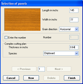 |
You must enter the formats of panels given in the second table in the section "The cutting list chosen for example".
You must change the values of the default panel. Enter the length, width, thickness of the panel and select the grain direction and finally material in corresponding listboxs with the values given for panel 1. |
||||||||||||||||||||||||||||||||||||||||||||||||||||||||||||||||||||||||||||||||
| < Previous | |||||||||||||||||||||||||||||||||||||||||||||||||||||||||||||||||||||||||||||||||
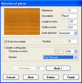 |
You must enter the sizes and quantities of parts given in the first table in the section "The cutting list chosen for example".
Enter reference, designation, length, width of the part and then select grain direction, thickness and finally material in corresponding listboxs with the values given for part 1. |
||||||||||||||||||||||||||||||||||||||||||||||||||||||||||||||||||||||||||||||||
| < Previous | |||||||||||||||||||||||||||||||||||||||||||||||||||||||||||||||||||||||||||||||||
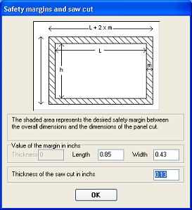 |
You must enter values for the margins Length and width and cutting thickness. |
||||||||||||||||||||||||||||||||||||||||||||||||||||||||||||||||||||||||||||||||
| < Previous | |||||||||||||||||||||||||||||||||||||||||||||||||||||||||||||||||||||||||||||||||
Result of the cutting optimization |
|||||||||||||||||||||||||||||||||||||||||||||||||||||||||||||||||||||||||||||||||
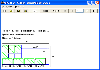 |
The panel cutting software shows the diagram obtained after the optimization calculation has done. The diagram shows panel by panel, the layout of parts. This layout is optimized by the software to limit the quantity of panels used and the number of unusable offcuts. It is possible to print the optimized cutting plan for use in the workshop then the diagram for the realization of cuts with a panel saw for example (see software user guide). |
||||||||||||||||||||||||||||||||||||||||||||||||||||||||||||||||||||||||||||||||
| < Previous | |||||||||||||||||||||||||||||||||||||||||||||||||||||||||||||||||||||||||||||||||
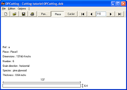 |
You can ask the panel cutting software to display the drawings of parts with these dimensions. It is possible to print the drawings of parts of the cutting plan if it seems useful to you (see software user guide). |
||||||||||||||||||||||||||||||||||||||||||||||||||||||||||||||||||||||||||||||||
| < Previous | |||||||||||||||||||||||||||||||||||||||||||||||||||||||||||||||||||||||||||||||||
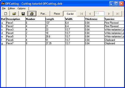 |
You can ask the panel cutting software to display the cutting list obtained after panel cutting software has done the calculation. It is possible to print cutting list for use in the workshop (see software user guide). It is also possible to export this cutting list to a file for reuse in Excel or other software. |
||||||||||||||||||||||||||||||||||||||||||||||||||||||||||||||||||||||||||||||||
| < Previous | |||||||||||||||||||||||||||||||||||||||||||||||||||||||||||||||||||||||||||||||||
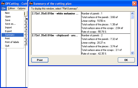 |
You can ask the panel cutting software to display the summary of optimized cutting plan (see software user guide). This summary can be printed if you wish. |
||||||||||||||||||||||||||||||||||||||||||||||||||||||||||||||||||||||||||||||||
| < Previous | |||||||||||||||||||||||||||||||||||||||||||||||||||||||||||||||||||||||||||||||||
|
|
|||||||||||||||||||||||||||||||||||||||||||||||||||||||||||||||||||||||||||||||||